
This is something I looked at 3 or 4 years ago and then forgot about. I used a CAD-style program that does element analysis and adds up magnetic force vectors. If you look at some of the Perendev-motor”work” by others on the net, there is the issue of finding an arrangements of the magnets so that they don’t find a local minimum in the gradient field and get “stuck there”; the solutions usually involved using multiple “rotors” (3 typically) with a staggered configuration of the outer stator magnets. I thought “why not stagger the magnets on a single rotor/stator pair in such a way that a single pair will never find a local minimum in a full rotation?”. The software (Vizimag) can tell you the total force vector on each magnetic element in the diagram.

The idea is that the outer ring would be fixed on an annulus, called a stator, and the inner ring would be on another annulus but attached to a rotating axis, which could drive a generator.
Given that the outer ring would be fixed, I used Vizimag to determine the x & y force components on each of the inner magnets, did some simple trig and got the total tangential force on the rotor. Because the tangential force from each magnet acts along the tangent of the inner annulus to which they’re attached, you can then just add them all up together and see if there is a non-zero tangential force in one rotary direction. Using parameter values for real rare-Earth magnets, Vizimag said that the total net tangential force on the inner rotor was in the hundreds of foot (not inches) pounds of torque, for a 12″ rotor with 1″ x 3″ magnets of typical “rare-earth magnet” Gauss strength, which I just looked up the value for on the web from a retailer for these magnets. The stator magnets are 1″ x 2″.
Some notes:
1) The total number of magnets is 33. I figured things are hidden within the number 33.
2) 15 magnets on the inside, 18 on the outside. Spaced equally with #3 below setting the referent.
3) The first inner magnet, the horizontal one in the upper right quadrant, points at the outer rim of the inner annulus at 32 degrees.
4) Other designs I read about had directly-facing magnets on inner and outer annuli. While this would cause repulsion in one direction if they were all perfectly lined up, it also automatically creates a local minimum, or balance, of force between the magnets, when they were angled “in between” each other. So the inner axis would just rotate into the intermediary position and then STOP, forcefully. This required 2 or 3 more disks /annuli combo’s to be oriented at staggered positions relative to each other along a connecting drive axis so that when one disk wanted to stop rotating, the others would keep on pushing.
5) Why not stagger the magnets on a single disk, then? That’s what I tried. The result being that as the inner rotor rotates relative to the stator, while the total tangential force in the CCW direction does vary in magnitude, it does not ever reverse direction. If a few magnets start repulsing in the wrong direction, there are always more magnets of more total force pushing in the original direction.2
6) I emailed the guy who wrote the magnet force CAD software (Vizimag) and asked him if this set up actually would rotate. He said I was seeing rounding error. I don’t believe him. This mesh-grid for the element analysis is the finest the program will allow. I know how element analysis works. If his software has a rounding problem in the 100’s of pounds of force when each magnet’s force is only a few pounds, it wouldn’t work at all.
7) Therefore the best way to know is to do. I haven’t done but someone should, just for fun. Maybe it really wouldn’t work but hey, it is still fun garage tinkering. Some high-strength plastic could be machined to fit the magnets into. Etc etc, mechanical stuff.
8) The rotating magnets would cause huge EMF. It might be picked up by “authorities” as radio emission. Therefore, do the test inside a Faraday cage or out in the country far away from everything and then quickly and leave. The magnetic EMF might also have health issue concerns…so…might not want to get too near. It might also look like an EMP weapon…or, be an EMP weapon. It would create a ridiculously huge rotating vortex of magnetic energy flowing out along the axis when spinning at a few thousand RPM…
10) If it actually does rotate, how long do the magnets last? How permanent are permanent magnets? How much energy does it take to create/produce a synthetic permanent magnetic vs. how much energy do you get out of this design hooked up to a generator? For all the people wishing for a free energy machine…well…go ahead and try and let us know the results, hehe. You can use this design freely.
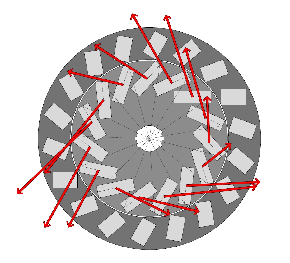
Force vector results from the element analysis. The stator magnets are supposed to be 1″ by 2″ in this diagram. This is just one rotation angle which was calculated for the force vectors for display here – an entire rotation was actually calculated in increments of 1 degree and all angles resulted in a net tangential force similar to above…in the same direction.
The next two images are GIFs and should animate – if they’re not animating then click on them or open them in a new tab…they might take a minute or two to download all the frames.

This is a .gif and it should animate; if it isn’t animating, click on it and see if it does on the new page. Might take a minute to load as it is a large file.

This is a .gif and it should animate; if it isn’t animating, click on it and see if it does on the new page. Might take a minute to load as it is a large file.
Anyway, just posting this here because I had it lying around on my desktop for the last few years. I honestly don’t know if it would work or not. The magnetic force analysis says it would, but hey, models are hardly anything to go by!

Fascinating. I wonder if the software is just completely borked. That’s a huge amount of power it is predicting. Is there any other software out there you could ‘replicate’ the ‘experiment’ with?
[JP Reply: I don’t know…last time I checked there wasn’t.]
If anyone built one of these and found it did start spinning up, it would be a good idea to have something ready to apply a load to it to minimise the shrapnel risk! A water pump brought in on a centrifugal clutch would be a good option. The outlet hose might come in handy to cool the thing down. 😉
Fun stuff, course, gotta remember the three rules: you can’t win, you can’t break even, and you can’t even stop playing.
Yah so for over-unity, you would have to have the result that it takes less energy to make the magnets than you get out with the system powering an electrical generator. The problem is that people believe “permanent magnets” are actually “permanent”, but, they are not. At least, I highly doubt they are “as permanent” as required. Of course, if they were permanent or “permanent enough”, then sure, you could get energy forever or more than it took to create the magnet. Someone should do it and quantify it all to finally put it all to rest…or prove it if they dare. I’ve never seen any of these designs actually scientifically quantified and tested, and there’s likely good reasons for that. But hey, as I said, I haven’t seen it, so, here’s to seeing it!
This guy’s good fun: http://jnaudin.free.fr/index.htm Ever visit his site? Warning – just as big a fan o crappy ambience music as the above!
Oh hey yah I remember that site…looks like in 3 years he never finished his overunity project…
I think he has been on it a bit more than 3 years.
Nicely put Max. Shades of Chaucer’s Canon’s Yeoman’s Tale.
With these machines, there is always a physical magnetic gate that mechanically holds X, therefor in order to move past X there will need to be extra force which is mechanical movement outside the machine to over come the gate, you could try it with springs but this will only delay the eventual halt of momentum.
Hi Joseph,
Have a look at the new type of electric motors developed by LeTourneau.
:-
Switched Reluctance (SR) Motors and Drives
http://www.letourneautechnologies.com/mining/sr_motors_drives.php
Rare-earth magnets are used extensively in the modern scale electric aeroplanes. You may know that China, with the one-child policy, has a model aeroplane (and all toys for that matter) boom, a bigger market than the USA, with parents and grandparents indulging their grand children.
The rotor is fitted with rare-earth magnets and the stator uses IC switched electro magnets.
The odd v even alignments of magnets on the stator and rotor is at the heart of these motors.
Oh wow interesting. Thanks for that info Loodt.
Permanent magnets do ”run down” eventually and with use the power drops quicker. The opposing force in these ingenious ”motors” counters the magnetism in the bar magnets so reducing their power.
You can’t get owt for nowt. Good try though.
Harnessing Radiant Energy Could Be the Answer To Our Dwindling Energy Sources
From all of Tesla’s patents for many of his inventions, none had greater potential to benefit everyone on earth than his discovery regarding Radiant
Energy which is the energy found in electromagnetic waves.
Not until recently was the potential of this discovery of
Radiant Energy fully exploited to be able to practically use this radiant energy to produce free energy & electricity for the use in
any household.
See a working model of Tesla’s free energy device in action producing electricity…
I enjoyed this http://www.youtube.com/watch?v=7PDeK6rprA4
While having access to a laser cutter, I’ve decided to construct a working model out of your description.
Only got a few questions: How did you figure out that 33 was the right number of magnets?
And how about the angle 32?
Hi Spiril1.
I guessed. Then I found that it worked (in the simulation) and so stuck with it. Would be happy to see your hardware/model and discuss it with you, and see what it does!
If your laser cutter can take a pdf diagram for instructions (some of them can), then you can use this. The inner portion is for an axle but maybe it is too wide…I can make the axle diameter smaller.
Hi Joseph.
Thanks for the quick response.
I’m going to make the model in some sort of PVC. (transparent = no hidden cheats 🙂
I’ve made my own instructions in illustrator and while I got a few other ideas I need to test live, I’ve changed your design a bit. Don’t think it mess up your calculations though.
Hopefully I’ll have a working model by the end of next week, and I’ll leave you a message after that.
Sounds good Spiril1. Care to show me the modifications so I can see if I think it will affect anything? Good idea on the PVC. It would be amazing to see if this thing rotated right away (model says it should…but we’ll see) cause that would make you and I (or just you 😉 ) famous for actually demonstrating a working model. Then you could see what power you can get out of it etc. At the very least, we can finally demonstrate a debunk of the concept which would be valuable in itself…cause you can’t really find that out there either.
🙂 If this thing works all logic says that it would already have been invented 😉
There is that, and sometimes I use that argument for other things…the danger, however, is if we argued like that all the time, nothing new would ever be invented!! 🙂
If you’re able to check it out and finally put it to rest on Youtube, you’ll be doing more than anyone else has with it.
Agree. And I’m just one of those Curious Georges that have to see it for myself.
Actually I’m most of all amazed that something that is so easily prooven (or not) can take up so much space in peoples minds – and on the internet.
This, and then my sence of logic that tells me, that your calculations just might be right.
will it work with smaller sizes of magnets?
It should/might. The magnet dimensions had an effect on the total torque result…but it just needs to be tested. What is most important here is the staggering alignment, and the spacing. If you have smaller magnets maybe the disk could be scaled down a bit.
The over all concept is correct, But the Heat and excess Magnetic Wave or pulse energy will be a problem and your correct “Its Nothing to Play With” you might be able to channel some of the energy off with a coil blanket to draw off the extra energy or you could rechannel it like the pulse wave guys are doing to give the rotor an extra kick, Now as a kid back in the late 50s I read stuff like Boy Experiments etc, So I once took permanent magnets and put a bunch of them on a Lionel train transformer and the Train ran like a scalded dog but the transformer got hot as heck and suddenly the magnets started dropping off the housing, And I found after that the magnets would no longer stick to anything like they just lost their strength so naturally I lost interest as i see that opposing force machines are not really practical but I once did an experiment with a attractive force machine /single force rotor/ and it spun but poorly but one time when I varied the angle the Rotor just got out of control and ran wild so I ad this as a warning since it clear we are getting into areas and forces that men can only dimly understand and I’ve heard on the web where one person did have a rotor -Explode- on him and he got schrapnel in his face tho I dont really know if his rotor fragmented or the latent energy just exploded it?.
So just a word to the wise here if you are Really gonna build this stuff to be care as the price of progress should never be anybody getting hurt and to close:
Good Luck In Your Quest:
Frisco Joe…….
Yah agreed given the torque that can apparently be generated with the correct angles, etc., this thing could “take off” and be extremely dangerous – rapidly moving parts after all. Yes I would think that with such a rapid changing magnetic flux, you’d heat up those magnets pretty quick, and then they’d demagnetize. Well, I wonder though what would happen if you put a big “load” on the thing to keep the rotation rate slow, maybe they wouldn’t heat as much, and maybe it would be less dangerous. Would need a pretty big load though, and maybe a massive electrical alternator/generator could be that load? Anyway, I have the drawings, and will give them to anyone who asks, if they want to build it.
Thanks for the comment and description of your experiences, Joe.
Thanks for putting a spot on some issues of the Perendev project.
My first attempt of constructing a device was no succes. No spinning of any kind. Actually it would do just fine as a magnetic brake.
While I figure that the problem (and solution) is hidden in the angle of the magnets, I am now designing a device where magnets can be set at any angle and possibly also with some way of adjusting the distance between inner and outer circle. I’ll let you know when I get further with the project.
Regarding your issues; overheating and magnetic pulse I consider these as the actual potential of the device. Besides from the mechanical adjustments mentioned above, the obvious way of controlling the spin/heat would be to attach a generator. I also consider some sort of wireing of the individual magnets which could possibly absorb some of the excess magnetic flux.
As for the outer shielding of the device I intend to use the principles of the “Rodin coil”.
PS: Sorry for my poor English.
Dear Joe, can you kindly send me the vizimag file. I am building this on an 8″ sprocket wheel, with .5x.5×2″ N48 magnets. It would help me estimate forces on each magnet vs different angles, Best wishes, Ali
Sent @Ali.
Hi Joseph and others.
Tested the Wheel above. The only result is, that it makes an excellent magnetic brake!
I further made the angles between magnets and distance between outer an inner circles adjustable but with no better result.
As I see it, the only thing left to test is with the use of a different size of magnets but I really can’t see, that would make any big difference.
Good luck thougt. ;ø)
fascinating thread! I would love to see the schematics for any of the devices you are all proposing. The Ancient Future Mystery People’s Pirate Academy would very much like to apply its alternative energy students to this project.
Hah!
http://www.afmppa.com/
http://www.pirateacademy.org/
http://en.wikipedia.org/wiki/Mu-metal
http://www.keelynet.com/news/indexapr13.html
scroll down to: “04/16/13 – Wardle – Magnetic Shielding material using silver”
Peace.
Interesting.. It seemed in the Perendev model some form of shielding was being used… perhaps wrapped around the rotor magnets in order to localize the repulsive force… I wonder if doing some judicious shielding on either the strator magnets or the rotor magnets would help?
Just upon curiosity. This Perendev motor design may require some kind of initial external force to turn the rotor to a certain RPM before it can really achieve sustaining or perhaps output some power. The torque required to turn the rotor is high initially (when it is completely stopped). Once a certain RPM is reached, the external force applying to the rotor may not be needed.
I think that would be called cheating AndyF.
It should be very easy to reproduce a very small version of the Perendev-motor. Just Use AutoCad to make 3d model of the magnet stator and rotor providing pockets for the cylinder shaped neodymium magnets and bearings. Send the file to Shapeways and in 3 or 4 weeks you should be able to prove or disprove the motor. if you could send me the detailed drawings or exact dimension of the Model, I would be happen to give it a try.
After seeing failed attempts at the Perendev-motor vs. seemingly successful ones. its obvious that the major difference between the two is a very fine level of calibration. “wooden or recycled computer parts” vs. “finely calibrated nylon, plastic or machined stators & rotors”. I agree with Daniel Batchelor. — On a smaller scale, with tiny magnets, this would make a great (and low cost) 3D printer project, provided the material can hold up to the structural forces. And if you were off by 2 mm, you could make variations/adjustments, and just reprint the stator and rotor. Also, with smaller magnets, there would be lower structural forces required by the material. I wonder if you could make one that is as small as a D-sized battery? I guess if you wanted, you can merely transcribe the dimensions from the GIFs above, and start from there.
One other thing I’ve noticed on some of the PMs that seemingly work (online), the magnets seemed as if they were trimmed to an angle on one end. I’m assuming this is so they can achieve closer proximity to the opposing magnet, or provide a shaped force. Perhaps this is yet another fine calibration. The closer you get, the higher the force that is exerted (squared).
Regarding to what Joseph E Postma said about “Cheating” by starting the motor rotation by hand to get it going – Well that’s no different than an electric starter on the car you drive. My snow blower, gas generator and lawn mower all require a pull, or electric starter too. ;^) So did Model T’s – they all had a crank start, which were far more dangerous than you might think.. http://www.mikecastruccifordmilford.com/blog/start-a-model-t-without-breaking-your-arm/.
The magnets Will loose power after two Months or something…but I believe there is a workaround (i.e. as a way of a *’shield’* from magnet loss): ***METAL WILL ACT AS *ANY* POLARITY*** (POS OR NEG FOR ‘ATTRACT’ OR ‘REPEL’) WHEN THE METAL TOUCHES THE MAGNET. Note: If the magnetic metals (regardless of pos or neg of attract or repel!) touch each other, then they will stick, so they can’t get too close! And also, it does lose a little strength when you do this! I don’t know why they don’t tell you this, but try this mag metal polarity for yourself, it will not fail, but the testing for longer than more than two months by this metal shielding awaits a mystery to be discovered !!!!!!
I have been enjoying reading this thread! Time will tell as to whether the desired result can be achieved in any design, but I think there is a reason why so many people are pursuing this goal … there is something instinctively missing from the limitations of classical physics! I have recently been working on a design similar in many aspects to this concept. I agree that there is a need for asymmetry (drive/repulse) that is key to any success. However I feel less is more when it comes to the number of magnets to be utilized. The diameter of the stater and rotor combination to be used will set this theoretical number of mags. I believe it is very important to limit the radial proximity of magnets to a minimum of twice magnet length regarding stator magnets, and positive poles vs negative poles the same limitation for stater to rotor. The concept being that magnetic eddy currents be eliminated or at least greatly reduced. As for magnet life, with Nedfeb magnets the elimination of eddy currents should allow them to maintain a very long life as long as operating temperatures are kept below that specified limit identified by the manufacturer. Finally, as everyone doing any experimenting in this area already knows, finding a method of lessening or eliminating Back EMF during rotation is very significant.
Yes back EMF is why these shouldn’t work. If you could eliminate back EMF…well not sure if that is possible!
I have been experimenting on permanent magnet motors for years.
My latest experiments have been with “one poled magnets”!
Whilst we know that there is no such thing as a one poled magnet, I am getting the EFFECT of a unipolar magnet.
Using 2 inch x 2 inch x quarter of an inch thick Neodymiums, I covered one face and four edges with 6 mm thick steel pieces, leaving the North face fully exposed.
This provided about 60 gauss out the “back” 2 inch x 2 inch face, whilst the fully exposed face outputted over 1,200 gauss, effectively making pretty much a one poled magnet.
When a rotor face (fully exposed side) has a stator magnet also with a North facing it, you get ATTRACTION and NOT repulsion!!
The rotor magnet then gets attracted towards the stator mag, from 60mm away, accelerates on its own and overshoots the stator magnet with almost no arresting force. It then carries on a considerable distance. Maximum gap between stator magnets is 60mm or you DO get approach repulsion.
Anyone interested in more details can contact me at stebra@xtra.co.nz
Steele Braden.
Okay, I built one. Doesn’t work. Locks in the “intermediary position”. However, I used magnets all the same size and strength, 15 in and 18 out, neodymium. Perhaps that is a mistake. I will try using smaller magnets on the stator and see what the results are. Stay tuned.
Post some pics Darrell!
I have also tried such a simulation in FEMM software several months ago. I calculated the torque on different magnet layouts, but the result was always the same. In some positions of rotor the torque is clockwise, in the other counter-clockwise. The function of torque in angle is sin-like one with the period equal to angular difference between magnet spacings of stator and rotor. The work is integral of torque on angle, so it is equal zero…
Pingback: พลังงานแม่เหล็ก « Kunawut's knowledge blog
can any one tell me..if i used N48 magnets..18 magnets on stationary plate..15 magnets on rotary plate.. n used 3 plates.. what rpm i get??..
No one knows.
I had the same idea but using the same size magnets on stator and rotor, i haven’t done a FEMM analysis but this is interesting.
I was really surprised! I also have similar idea and my designed motor has total of 33 magnets, but 18 magnets on the rotor and 15 magnets on the stator. I guess the rotor will lock in some position, when reaction forces of the 33 magnets are balanced.
However I am going to bet on that little possibility for fun. So I’m making the motor right now, then I’ll upload the result of my experiment to the YouTube.
hello sir.
as you have shown in software, it rotates and produces power. If we make prototype of same this type 15 magnets on rotor and 18 magnets on stator, does it will rotate? and please can you tell me the exact size of magnets and which types of magnets you have considered for this project? and which calculation you have considered for magnetic force?
kindly reply.
thank you
Hi, if you still have schematics for the degrees and positions etc of the magnets, i would love to get my hands on em. Im CNC worker from finland and love to explore things like this 🙂 Its hard to draw inventor pics without the actual information. Thanks !
couple of things I have noticed on magnet motors that claim to work are 1 the stator magnets
appear to be in a horse shoe configuration and all have magnet keepers.
Quite interesting simulation!
I’m wondering about the comment regarding the “intermediary” position, where the rotor is locking. If it’s not visible in the simulation with the 1degree steps, (and we assume no rounding errors), this means step size is still too large. Can someone do a simulation with a much finer step size, like 0.001deg? It’s probably sufficient to simulate 1/15 of a full circle. Maybe it’s possible to find this “intermediary” locking position by iterative simulation runs and have a look a the force vectors around this point. Seems like this point is very small/singular, but if in turn the vector sum is incredibly large, real life would still integrate and in sum brake down the rotor in longer runs.
Maybe someone with better physical knowledge can calculate/integrate the forces analytically?
That could prove where the energy is coming from: if the force integral is 0, it’s coming from the initial external “start-up” rotation some people say is necessary, we can’t get much energy out of it. But if the integral is unequal to 0, the energy is coming from the magnets themselves
about the “horse shoe” – maybe that’s the way to get around that “intermediary” locking position and change the vector sum.
about the “keepers” – how are they built? are they additional magnet or metals? not sure, but maybe they are used to help relaxing the field lines? Because from the simulation it looks like many field lines actually come out of the magnets at an angle much larger than 90deg, which sounds like difficult to obtain in reality. So maybe we can get the “keepers” into the simulation by specifically placing them to relax the angle of the field lines.
not sure this makes sense though 🙂
Is these Magnets wheels are for sale ?
My email – lanteigneedgar@gmail.com
Pingback: Questions They Don't Want You To Ask About The Global Power Outages
If anyone is interested, I have a copy of the Perendev Power Developments video from 2003 shared here: https://drive.google.com/file/d/12KpwlNa4quyZR3F1f3jdiAlBnXfPWTjp/view?usp=sharing
2.5MB
Oh nice!!
Thanks for posting that Alex! Wow, does that bring back memories! That was the video I based the design off of, using a magnetic field element analysis program to see if it could actually generate torque, because we calculated from equations in school that a net magnetic field loop couldn’t do so. But with the staggering, I think that you can make it work! It doesn’t work, sure, when you have symmetry, but the staggering creates asymmetry and then I think that it will work. Actually my design made it so that it would generate torque even with a single stator and rotator because I built the asymmetry right in between the rotator and stator.
Yeh. 22 years ago! I was surprised to find it on my system. Your subscription email reminded me of it. I was going to try to build a miniature one back then in my machine shop, but running my business and raising my daughter took presidence. This thread is very interesting. Lots of stuff I never thought of.
Chat gtp suggests this setup to create torque
That would do nothing I think. It would stop in the middle.
✅ How to Break Symmetry & Avoid Locking?
Here are proven methods (used in experimental designs and magnetic tricks) to keep motion going:
1. Asymmetric Magnet Arrangement
Idea: Shift the position or strength of magnets to make the field unbalanced.
📌 Result: The rotor constantly sees a net push or pull in a specific direction.
2. Shielding Magnetic Zones
Idea: Use magnetic shielding (like mu-metal or soft iron) to block or redirect the magnetic field at strategic locations.
📌 Result: The rotor escapes the trap and continues rotating.
3. Cam Mechanism / Mechanical Timing
Idea: Use a mechanical cam to temporarily move stator magnets away as the rotor approaches.
📌 Result: Like a ratchet — forward motion is easy, backward motion is blocked.
4. Tilting or Angling Magnets
Idea: Tilt magnets to create non-radial forces that curve the force vector into rotation.
📌 Result: Converts repulsion/attraction into tangential torque.
5. Use of Magnetic Gates (Halbach Arrays)
Idea: A Halbach array enhances the field on one side and cancels it on the other.
📌 Result: One-sided magnetic pressure helps rotation, resists reversal. 💡 Visual Idea (for a future diagram):
Imagine a circular track with:
🧠 Bottom Line:
⚙️ What Is Active Switching?
It means controlling the electromagnets (turning them on/off or flipping polarity) at the right moment to push or pull the rotor in a consistent direction — just like in brushless DC motors. 🔄 How It Works Step-by-Step 1. Position Sensing
2. Timing the Electromagnets
3. Repeat for Continuous Motion
🔌 What’s Needed ✅ Components:
⚡ Real-World Example
This is exactly how brushless DC motors (BLDCs) and stepper motors work:
Here is a high efficiënt hybrid setup. Could try it in the Perendev style layout
Little bit cheating tho with 3 extra electro magnets. No perpetual free energy
Both stator and rotor have permanent magnets. The stator has toroidal type permanent magnets and also have 3 electro magnets. The rotor has 4 sides, using neodymium magnets.
Here is a home made switch controller with 3 sensors. What controls in rotating order which one of the 3 electromagnets gets switched on
Nefunguje to! Vytlačil som to na 3D tlačiarni, použil som menšie magnety, lebo som nechcel investovať veľa peňazí do niečoho, čo nemusí fungovať. Ono by to fungovalo, keby sa odrušilo magnetické pole z bočnej strany magnetov.